|
DIY HYDROPHONE ELECTRONIC CIRCUITS Pre-amp and Amplifier Physical Layout My Squelch page also includes a circuit relevant to hydrophones Frank Watlington's Pre-Amp Circuit
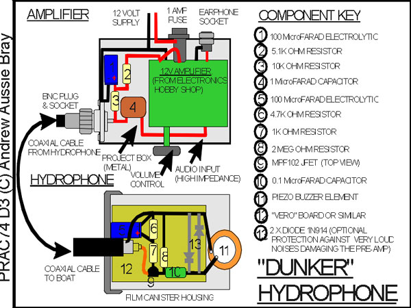
The above pre-amp circuit is the one I use with both dunking and towing DIY hydrophones. The left hand side is potted in epoxy and housed with the hydrophone Piezo element. The right hand side is on board the boat, but linked to the hydrophone via the cable. The output of this pre-amp circuit needs further amplification before it can be heard in a very small loud speaker or headphones. For loudspeakers a third stage of amplification is required. The diagram below shows the physical layout and components for a dunking hydrophone using the above pre-Amp, and to minimise the amount of electronics involved, assumes that an off-the-shelf amplifier (see links) will be used to boost the pre-amp signal to a high enough level to be audible in headphones, or an earphone. Below this is a circuit for such an amplifier based on the LM380 Chip, which is not difficult to build, and is what I actually used in my first hydrophones.
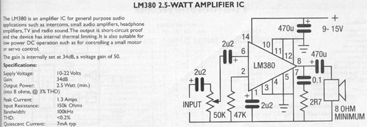
Link to list of Components with Jaycar Part numbers in html format Link to list of Components with Jaycar Part numbers in Word format The Amplifier Circuit reproduced below is from the "Dick Smith Electronics" catalogue (Australia) and is the one that I used for my first DIY hydrophones. The output from the pre-amp circuit was connected as the input to this circuit, and the audio output from this amplifier circuit was connected to a mono headphone rather than the 8 ohm speaker shown in the catalogue circuit. This and the pre-amp can be powered from a single 9 Volt dry cell battery, or from a boat's 12 Volt supply. The 12 Volt should be regulated (to 9 or 12 Volts) using a voltage regulating chip if the system voltage could exceed 15 Volts. The LM380 chip and regulating chips are commonly available from electronic hobby supply stores, as are the resistors and capacitors, and piezo buzzers from which the ceramic piezo element can be removed. Making a PCB The electronics for these little circuits can be readily soldered together using project boards pre-drilled with a matrix of small holes, with or without copper around the holes on one side of the boards, and short insulated wire links. Electronic hobby shops also offer blank PCB with a copper layer all over one side. These can be used to make circuit boards by etching away the unwanted copper to leave just the tracks needed to interconnect the components. The result is a neater project. I did this for the above amplifier circuit, incorporating locations for a voltage regulating chip and and my first attempts at a squelch circuit. The circuit was not a success, but the method of producing a PCB from artwork was satisfactory, despite my amateurish artwork. There are various ways to do the etching, but I used a laser printer to transfer my layout artwork onto "Press-N-Peel" film. The film was then ironed onto a piece of blank copper PCB, leaving a plastic version of the artwork adhering to the copper. The board was then etched in Ammonium Persulphate to remove the exposed copper, after which the plastic protecting the circuit was peeled off to re-expose the copper circuits.
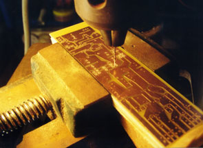
The photo shows the final step - drilling holes for the components in the PCB. I used CorelDraw to prepare my artwork, which isn't designed for that job and was a laborious process. I've since tried several shareware programs that can be used to produce artwork for small PCBs. EagleCad was the most sophisticated that I came across, with the largest library of standard components. It was recommended to me by Ricardo Paez in Chile, who successfully built one of my DIY hydrophones, and then added a short range FM wireless link to it, so that other students on the boat could tune in the hydrophone on their portable radios. His PCB layouts look professional, but I found EaglkeCad procedures counterintuitive, and without a tutorial I couldn't make practical use of it. ExpressPCB is one of many programs available from specific board manufacturers, and was used to produce the schematic in my Squelch page. I found it easier to get to grips with, but its small library of standard components meant I had to draw many components manually, with distinctly unprofessional looking results!
|