Hydrophone Squelch
In an earlier version of these web pages I mentioned that I’d like to be
able to fit a squelch control to my hydrophone amplifier output, so that I
wouldn’t have to listen to the background noise during long hours at sea,
but would immediately hear any stronger signals such as whales or dolphins
in the area. Many communications radio receivers have an adjustable
muting
function, which is called a "squelch" control. I initially
attempted to build the squelch into the amplifier, making use of the mute
pin on the amplifier chip, but couldn't get a level detection system that
worked satisfactorily.
Ron AAlst in Holland
raalst@bart.nl then suggested several approaches for a stand-alone
squelch system. The squelch circuit
described here is based on one of Ron's suggestions, with the momentary switch function added by my son Chris
(an Electrical Engineering student at UNSW in Sydney). It works well with
my hydrophone, and although a PCB design would make construction easier and
neater, the circuit is quite straight forward to build on a piece of
project board, and the components aren’t very expensive. So if you’ve a
need for a stand-alone squelch circuit (not necessarily just for hydrophones) – be our
collective guest. If anyone out there produces a PCB layout I’d sure
appreciate a copy of the artwork, and any suggestions for improvement or
modification are welcome. My own very limited experiences with PCB layout
programs are mentioned
here
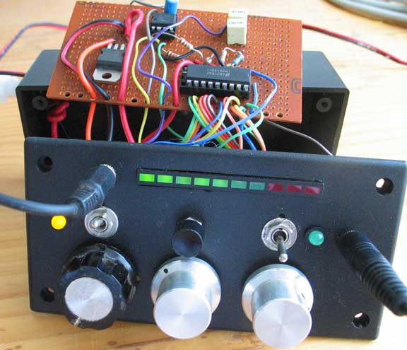
The photo shows my as-built experimental unit - the circuit
below incorporates a few refinements added later.
Function Overview
This device is literally a “black box”, connected by plugs and cables
between the output of the hydrophone amplifier and the speaker (or another
amplifier stage). It monitors and displays the arriving signal and
only connects it through to the speakers or next amplifier stage when the
signal
exceeds a set threshold. The presently set signal threshold level can be viewed
on the bar graph by depressing the momentary
switch (round black button in the photo) and adjusted by simultaneously rotating the Level Select knob (left
hand silver knob). If
the device is turned off the signal is passed directly to the output
socket, so no power is drawn if one wishes to listen to the hydrophone
without the squelch working.
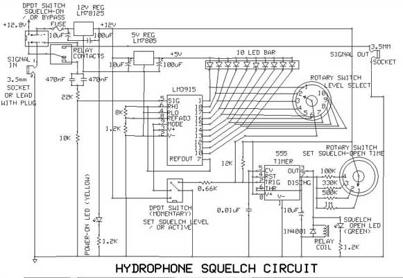
Circuit description
The whole unit is intended to be powered from a well charged 12Volt
battery (nominal 12.8V). The current passes through an on/off switch
(which also switches the signal into the unit) and fuse to a 1 Amp 12 Volt
regulating chip which powers the rest of the circuit except for the LED
bar, which is powered via the 5 Volt regulating chip. (This LED bar could
also be just a line of ten independently mounted LEDs) The signal enters via a
3.5mm mono plug and socket, and a pair of 470uF capacitors filter out any
DC component so that just the signal reaches the LM3915 chip.
This chip is purpose designed to drive LEDs in response to changing
signal levels. As configured in this circuit, it operates as a bar graph ,
responding to the varying input signal (it also has a moving dot mode). The 8K and 1.2K resistors set the
internal reference voltage that the chip uses when determining signal levels. The
photo shows my as-built version, which included a variable resistor
controlled by the black & silver knob, but
these fixed values work ok with my hydrophone. Download the
LM3915
datasheet if you’d like to know more about the chip.
In Bar mode, the stronger the signal the more LEDs are lit, starting from LED 1 (at a
signal level of -27dB with respect to the reference voltage) and
progressing to LED10 (0 dB) in 3dB intervals. Five volts is continually
applied to all the bar LEDs, and the chip turns each on when required by
connecting the appropriate pin to ground via internal resistors.
The first rotary switch allows any one of the outputs to the LED bar to be
selected as the threshold signal level used to trigger the 555 timer. If
the momentary switch is pushed, the LM3915 is temporarily de-powered and
the selected LED is connected to ground via a resistor. This turns on the
selected LED, allowing the present selection to be seen and adjusted. Once
the momentary switch is released, if the selected LED is turned on by the
LM3915, the voltage at the switch output falls, triggering the 555 timer.
The timer output is used to power the coil of a small relay (coil
resistance must be greater than 500 ohms). The relay connects the
hydrophone signal to the output socket, and simultaneously disconnects it
from the squelch circuit. [If one wanted to simultaneously view the signal
levels and listen, this disconnect function could be bypassed, but this
might drain away some of the signal] The relay remains in this condition for a time
interval and then switches back to the muted mode, unless the signal
remains at or above the set threshold. The period of time that the squelch
remains open can be adjusted between approximately 10, 5, 3 and 1 seconds by
rotating the On-Time knob (right hand silver knob). Increasing the size of the 10uF capacitor,
and/or the 1M resistor, should extend the time interval proportionately.
A double pole relay might also be used, which would allow the squelch to
turn on a recording device, or a further amplifier stage.
Return to top of this page
|