|
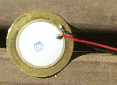
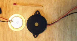
DIY DUNKING HYDROPHONE DETAILS Various types of hydrophones may be constructed, including some which could be used at great depth, but for shallow water use the cheapest and most sensitive are called "bender" hydrophones. The following diagram and photo provide information on construction of a simple DIY bender hydrophone, in a housing suitable for dunking over the side of a stationary boat - or even a wharf. It uses the piezo-ceramic element and attached brass disc and wires, extracted (taking great care not to scratch or flex it!) from an inexpensive audio transducer as illustrated below. Such transducers are available from electronic hobby suppliers (e.g. Audi Transducer catalogue # AB-3440 from www.jaycar.com.au for Au$3.60). Similar piezos are also found within electronic buzzers and even some talking greetings cards , but I don't know whether those buzzers having three rather than two connections to the piezo are suitable. As a buzzer or enunciator the piezo is made to vibrate by applying a rapidly varying voltage to it - but all these piezo elements can also do the reverse - produce tiny voltages that vary as sound waves "bend" the piezo.
In the example below, a transparent film canister has been used as the housing, but many other flexible containers are also suitable, including sauce squeeze bottles. In this instance the canister has a snap-seal, but the the rubber-weld tape prevents it opening if dropped. The optional "deflection limiter" protects the disk against cracking if the hydrophone is used too deep, but if a relatively short cable (3-5 meters) is used the limiter should be unnecessary. The various electronic components within the canister and inside the project
box form a pre-amplifier circuit, with the output signal and the power
supply to the pre-amp using the same pair of wires in the cable. The diagram
shows an external 12 Volt supply to the project box, which could come directly
from a boat's battery, or via a voltage regulating chip. The pre-amp circuit
will work over a range of voltages, and the unit in the photograph is
self-contained, powered by a single 9 Volt battery within the project box.
|